

Insertion Meter Installation Guide
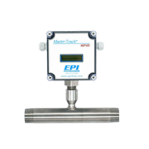
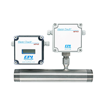
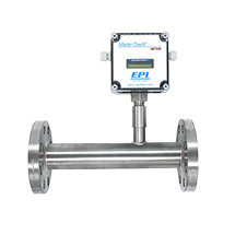
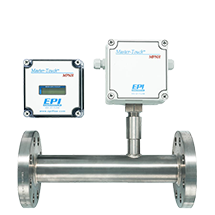
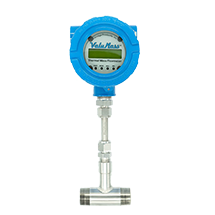
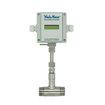
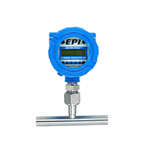
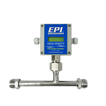
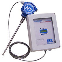
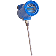
The insertion style flow meters include the flow sensing element, temperature sensing element, bridge amplifier/signal output board, microprocessor circuit board, transmitter enclosure, and the probe assembly which supports the sensing elements. This design requires the probe assembly to be inserted into the process gas flow conduit.
Insertion styles are available with 1/2″, 3/4″ or 1″ OD probes. Insertion style flow meters may be installed with properly sized bored-through tube fittings to mount them in place. Tube fittings, with or without mounting flange, are available from the factory as an option. Installing the tube fitting consists of preparing the flow conduit to accept the fitting by first drilling a clearance hole for the transmitter probe assembly, welding it in place, or threading it into the proper size half coupling which has been welded to the flow conduit. The tube length will be determined by EPI™ based upon the installation specifications.
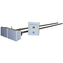
Optional ball valve assemblies are available through EPI™ which allow the removal of the insertion style averaging tubes for service, calibration, cleaning, etc. The valve provides a means to seal off leaks of the process gas at the point of insertion after the probe assembly has been removed. Installation requires fitting the flow section to which the insertion probe assembly will be inserted with a threaded half coupling of the proper size to accommodate the ball valve retractor. In some instances, this requires direct threading together (or with a reducing bushing) of the retractor assembly. In other cases, it requires welding the half coupling in place and drilling a clearance hole through for the probe assembly. If the flow section is under pressure, a hot tap drill rig (not available through EPI) may be required.
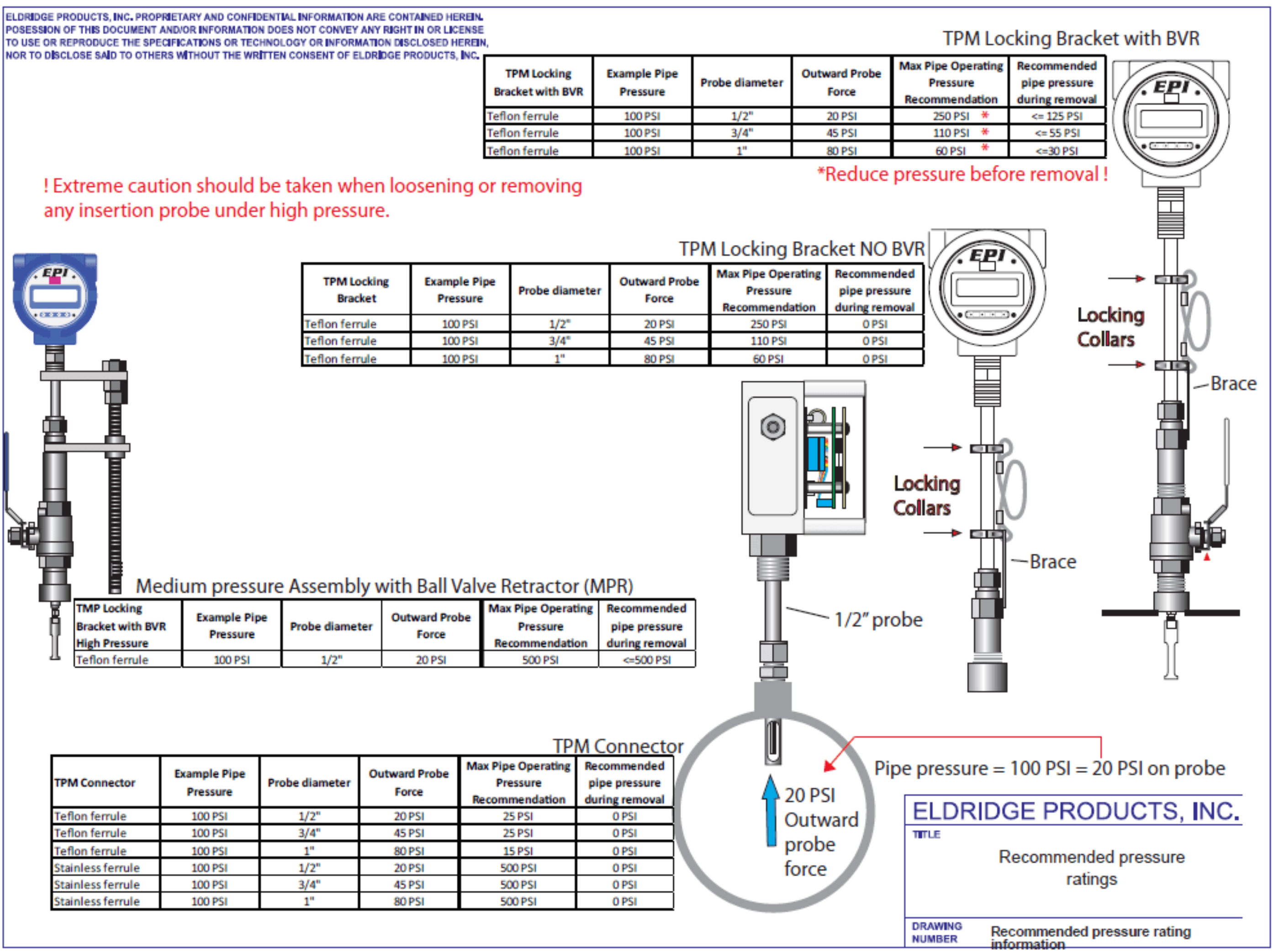
The maximum pressure for insertion style flow meters is stated in the Manual for each product. To reduce the possibility of personal injury when servicing the flow meter, each size is rated such that the maximum force applied to the transmitter is approximately 25 pounds. Caution should be exercised if considering applying higher pressures, and AT HIGHER PRESSURES, A HOLDING DEVICE MAY BE REQUIRED TO PREVENT THE TRANSMITTER FROM BEING PROJECTED OUT OF THE PROCESS LINE WHEN REMOVING OR REPLACING THE TRANSMITTER ASSEMBLY.
Flow Meter Installation: Probe Insertion Depth Guidelines
EPI calibrates insertion flowmeters for positioning near the ISO Point-of-Average-Flow (0.243r). See the installation manual for calculation of the probe insertion depth (pipe OD to probe end) includes the point-of-average-flow, the x-factor, and the wall thickness of each nominal pipe size, as well as a further adjustment on smaller line sizes to be sure that the slot is fully inserted through the pipe wall. Any potential blockage effect created by inserting the probe assembly into the pipe to the depth listed has been accommodated by EPI™ as part of the calibration for the pipe size specified for the initial factory calibration. Therefore, the factory C-Factor value is now always “1”. Product-specific insertion depths are included in the Manual for that product.
Consult the factory for any additional C-Factor adjustments required if the flowmeter will be used in a pipe size other than that specified for the initial factory calibration.